First Photo Of Tesla’s 4680 Battery Pack: Detailed Analysis

Preface
The photo we are analyzing was posted on Electrek without any sourcing, and it may be proprietary. Therefore, we can't show it here. But please don't tune us out. Follow the link to have a look, and then come back here for our detailed analysis. It really is a fascinating story.
Discussion
First, a quick word description of the photo. The photo shows what looks like a honeycomb structure with holes in it, presumably sized for 4680 cells. The spaces in between the cells are filled with some sort of epoxy that looks like the same stuff Tesla uses in the Model 3 pack. Along the edge of the pack, there are loops of tubing that could be for cooling. There are 960 total holes for cells and the holes are 24 by 40.
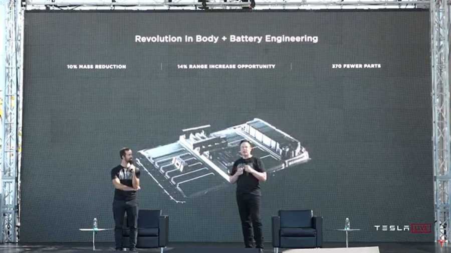
When we first saw this photo, we were totally flabbergasted. The first thing that stuck out was the large spacing distance between the cells. Totally unlike what Tesla has previously posted for the 4680 pack as shown below.
The second thing we noted was what appeared to be loops of flexible glycol cooling tubes along the edges of the pack connecting to the pack at every other row.
If we assume we are looking at a 46 mm diameter hole for a cell, and calculate the ratio between the hole diameter and the gap, the spacing comes out to some crazy large number like 9mm between each cell. With that spacing, and the 46mm diameter, it is simple to calculate what the dimensions of the pack are. The answer said, this pack was too long by around 6" to fit in a Model 3. It did have a perfect match on kWh's though. The 24X40 hole pattern is 960 cells and the energy calculates out to 84 kWh. Perfect for a Model 3 or a Model Y.
But the fact that the size calculation showed the pack was too big to fit was disturbing.
If you blow up the photo, what you see is not holes where cells go. What you are seeing is a domed cap. The domed cap is partially covered with foam on the outermost diameter. We assume the domed cap is put over the holes so when the foam is injected it doesn't go into the cell holes.
We then re-worked the size calculation assuming a 4mm cell spacing and 46mm diameter cells.
Bingo. It fits with just enough room on the sides for cooling tubes.
The 4mm spacing we assumed would be enough to squeeze in a cooling snake between every two cell rows just like Tesla uses in all its EVs. The problem is that we can see evidence of what looks like a plastic sleeve, which would be around each cell. The pack would be built in stages. Honeycomb structure down first, then the plastic sleeves, then the foam would be injected, caps then removed, and then the cells put in. If it is a plastic sleeve, this presents a problem with using a side cooling snake (lousy heat transfer).
Another possibility is that Tesla could put a flat cooling snake (which would technically be a flat tube since it doesn't have a sinusoidal shape) under each cell row. The cells would get a dab of epoxy on the flat negative end of the cell, then be inserted and glued to the cooling tube on the negative ends of the cells. The epoxy type would be the same stuff they use to glue the cells to the cooling snake in the Model 3. It is designed to have a good heat transfer coefficient. This would functionally be the same thing as a flat cooling plate but might save a little on height.
I know we have said before that these 4680 cells can't be cooled through the sides. That's true without the tabless electrode design. However, the tabless architecture gets most all the heat to the negative end of the cell and directly contacts the cell's steel containment "can," which can conduct heat to the sides of the cell and then to the cooling snake. We ran the numbers through our thermal model and verified sufficient heat transfer to allow side cooling, as long as the cell is tabless architecture.
So, the bottom line is that we don't know if Tesla is using side cooling with its conventional cooling snake or whether it's cooling the bottom negative end of the cell.
The final pack with 84 kWh's and a 24 by 40 grid is shown in figure 2.
Please note that the pack we are discussing here is not necessarily the configuration that Tesla will come up with in a "clean sheet" design. Since Tesla is shoehorning this pack into an existing Model 3, some compromises probably were made, especially if Tesla is height limited. Remember the 4680 cells are 10 mm (.394") taller than the 2170 cells. A "clean sheet" design for Cybertruck or the Semi might look different. Specifically, Tesla could use an engineered production flat cooling plate, not this cobbled up cooling snake design we have proposed here.
I know this all sounds pretty far-fetched. Especially the flat cooling snake.
Let us know what you think in the comments section.
Nouvelles connexes


